WinoBOARD the small, affordable, and wireless tool for your Internet of Things applications.
1. Quickstart guide
1. Download and install the Arduino IDE (latest Version tested: 1.6.9)
https://www.arduino.cc/en/Main/Software
2. Install the WinoBOARD Addin
-
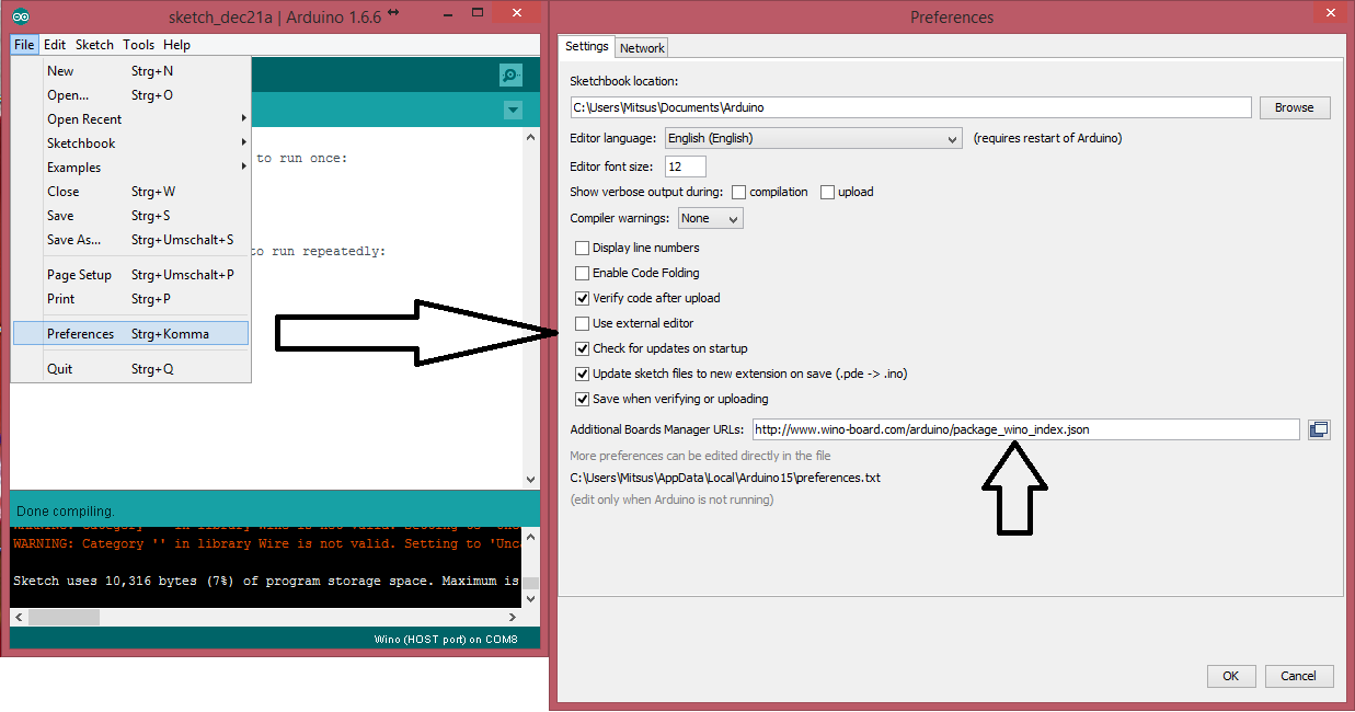
Start the Arduino IDE and change to
File->Preferences - Add following URL to the Additional Boards Manager URLs:
http://www.wino-board.com/arduino/package_wino_index.json
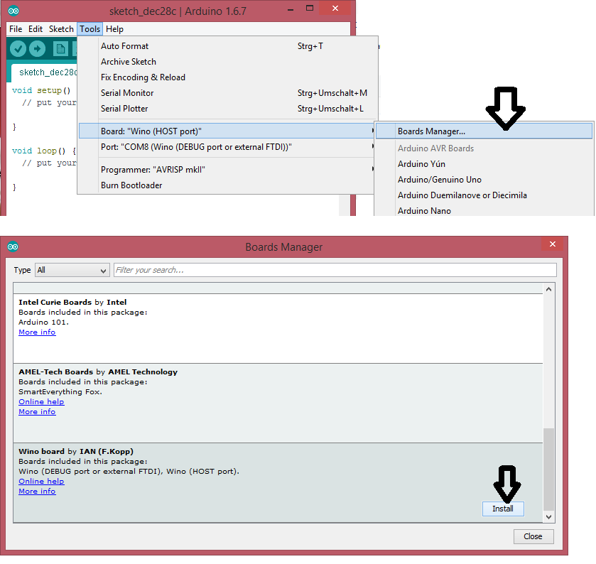
- Open the board manager by changing to
Tools->Board->Boards Manager - Install the WinoBOARD package (should show up last on the list)
3. Connect the Wino board
- Connect the WinoBOARD to an USB-Upgrade or Programming board
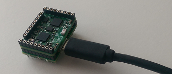
- Connect the board to USB
- Select the board
WinoBOARD [USB]in theTools->Boardmenu - Select the USB port in the
Tools->Portmenu
4. WIFI-Setup
-
power up your Wino board
-
connect to the wifi network calles "Wino board setup"
-
open up a web browser and change to page "192.168.4.1"
- select your wifi network and connect
After this steps your module will automatically connect to your network at each start.
For now please use the AT commands to control the WIFI module.
5. Upload your code
Please make sure you selected the Wino board (Host port) and the right COM-port in the Arduino->Tools menu.
You are now able to upload your code to the board. You can try one of the tutorials (work in progress) or try some of the existing Arduino tutorials out there.
This page also may help you to getting started in the Arduino universe:
https://www.arduino.cc/en/Guide/HomePage
Here is a simple LED-blink example and turning on WIFI module:
void setup() {
  pinMode(2, OUTPUT);
}

void loop() {
 digitalWrite(2, HIGH);   // turn the LED on (HIGH is the voltage level)
 delay(1000);              // wait for a second
 digitalWrite(2, LOW);    // turn the LED off by making the voltage LOW
 delay(1000);              // wait for a second
 }
2. WIFI-Library
The WIFI-Library is contained in the WinoBOARD-Addin for the Arduino IDE. To access the library please get sure you have selected the WinoBOARD [USB] board in the Tools->Board menu.
To use the library simply select Sketch -> Include Library -> WinoBOARD Library from the menu.
Or add this line on top of your code:
#include "wino.h"2.1. Basic functions
wifi.on(baudrate)
Turns on the WIFI-module
Example:
wifi.on(115200);wifi.off()
Turns off the WIFI-module
Example:
wifi.off();wifi.restart()
Restarts the WIFI-module
Example:
wifi.restart();wifi.info()
Returns a Version information of the WIFI-module as String
Example:
This code prints the Version info to the USB-Terminal
#include "wino.h"

void setup() {
wifi.on();
SerialUSB.begin(115200);
}

void loop() {
delay(2000);
SerialUSB.println(wifi.info());
}wifi.wait(timeout)
Waits until module is connected and TCP-address is received
timeout = timeout to wait in milliseconds
Example:
The module starts and waits until it is connected
#include "wino.h"

void setup() {
SerialUSB.begin(115200);
wifi.on();
  if (wifi.wait(15000)) {
  SerialUSB.println("WIFI is connected");
  } else {
  SerialUSB.println("could not connect to WIFI");
  }
}
void loop() {
}wifi.sleepmode(mode)
Sets the module in sleep mode to save energy
mode = 0 -> disable sleep mode
mode = 1 -> light sleep mode
mode = 2 -> normal sleep mode
Example:
wifi.sleepmode(2);wifi.sleep(time)
Turns the WIFI-module into deepsleep for a certain time (no WIFI connection available in this time)
time -> time in milliseconds (e.g. use 1000 for 1 second)
Example:
wifi.sleep(1000);wifi.getStatus()
Returns the current connection status as boolean
true = Module is ready
false = no response
Example:
This code prints the Status of the WIFI-module to the USB-Terminal
#include "wino.h"

void setup() {
wifi.on();
SerialUSB.begin(115200);
}

void loop() {
delay(2000);
  if (wifi.getStatus()) {
    SerialUSB.println("Module is ready");
  } else {
    SerialUSB.println("Module is not responding");
  }
}
2.2. Client mode functions
wifi.setMode(mode)
Sets the connection mode of the WIFI-module
0 = Client mode (The board connects to an existing WIFI-network)
1 = Access Point mode (WIFI devices are able to connect to the board)
2 = Client & Access Point mode
3 = Flash mode
Example:
This code sets the module to Client&AP mode
wifi.setMode(2); //Set to Client&AP mode
wifi.list()
Returns a list of found WIFI-networks as String
Example:
This code sets the module to Client mode and prints found WIFI-Networks to USB-Terminal
#include "wino.h"

void setup() {
wifi.on();
wifi.setMode(0); //Set to client mode
SerialUSB.begin(115200);
}

void loop() {
delay(10000);
    SerialUSB.println(wifi.list());
}wifi.join(ssid, password)
Connects to a WIFI-network
Example:
This code waits until the Module is connected to WIFI and prints process to USB-Terminal
#include "wino.h"

void setup() {
wifi.on();
wifi.setMode(0);
SerialUSB.begin(115200);
  while (!wifi.join("MyWifiNetwork","12345")) {   //please adjust name and password
    SerialUSB.println("connecting to WIFI...");
    delay(5000);
  }
  SerialUSB.println("connected to WIFI");
}

void loop() {

}
wifi.leave()
Disconnects from any WIFI-network
Example:
This code disconnects from WIFI network
wifi.leave();
wifi.getip()
Returns the current IP-address of the Client as String
Example:
This code waits until the Module is connected to WIFI and prints IP-Address to USB-Terminal
#include "wino.h"

void setup() {
wifi.on();
wifi.setMode(0);
SerialUSB.begin(115200);
wifi.join("MyWifiNetwork","12345"))   //please adjust name and password
}

void loop() {
delay(2000);
SerialUSB.println(wifi.getip());
}
2.3. Note: The maximum is 4 clients in AP mode.
wifi.setMode(mode)
Sets the connection mode of the WIFI-module
0 = Client mode (The board connects to an existing WIFI-network)
1 = Access Point mode (WIFI devices are able to connect to the board)
2 = Client & Access Point mode
3 = Flash mode
Example:
This code sets the module to Client&AP mode
wifi.setMode(3); //Set to Client&AP mode
wifi.config(ssid,password,channel,encryption)
Sets the AP mode configurations of the WIFI-module
encryption:
0 = open
2 = WPA_PSK
3 = WPA2_PSK
4 = WPA_WPA2_PSK
Example:
Coming soon
2.4. TCP/UDP Client functions
wifi.connect(mode, IP-address, port)
Connects to a TCP/UDP-Server port
mode
TCP = TCP/IP-Protocol
UDP = UDP-Protocol
Example:
This code connects the module to an TCP-Server
wifi.connect("TCP", "192.168.0.10", 7777);
wifi.disconnect()
Disconnects from any TCP/UDP-Server
Example:
This code disconnects from the current TCP or UDP connection
wifi.disconnect();
wifi.writeln(data ) -> For normal mode if one connection is open
wifi.writeln(Connection-ID, data) -> For multiple mode if more connections are open
Sends data to the connected port
Example:
Coming soon
wifi.readln(data ) -> For normal mode if one connection is open
wifi.readln(Connection-ID, data) -> For multiple mode if more connections are open
Sends data to the connected port
Example:
Coming soon
wifi.write(data, Data length ) -> For normal mode if one connection is open
wifi.write(Connection-ID, data, Data length ) -> For multiple mode if more connections are open
Sends data to the connected port
Example:
Coming soon
wifi.read(data, Data length, timeout ) -> For normal mode if one connection is open
wifi.read(Connection-ID, data, Data length, timeout ) -> For multiple mode if more connections are open
Receives data from the connected port
Example:
Coming soon
2.5. TCP/UDP Server functions
wifi.connect(mode, IP-address, port)
Connects to a TCP/UDP-Server port
mode
"UDP" = UDP-Protocol
"TCP" = TCP/IP-Protocol
Example:
This code registers a UDP port
wifi.connect("UDP",7777);
wifi.start(port)
Create a TCP/UDP-Server port
port = port to listen as integer
Example:
This code creates a Server which listens to port 7777
wifi.start(7777);
wifi.stop()
Close TCP/UDP-Server
Example:
This code closes the server
wifi.stop();
wifi.writeln(Connection-ID, data) -> For multiple mode if more connections are open
Sends data to the connected port
Example:
Coming soon
wifi.readln(Connection-ID, data) -> For multiple mode if more connections are open
Sends data to the connected port
Example:
Coming soon
wifi.write(Connection-ID, data, Data length ) -> For multiple mode if more connections are open
Sends data to the connected port
Example:
Coming soon
wifi.read(Connection-ID, data, Data length, timeout ) -> For multiple mode if more connections are open
Receives data from the connected port
Example:
Coming soon
wifi.getipStatus()
Returns the status of a current TCP or UDP connection as String
Example:
Coming soon
wifi.getDevices()
Returns an list of current connected IP´s as String
Example:
Coming soon
wifi.setTCPServerTimeout(timeout)
Changes the timeout for TCP-Server connections in Seconds (default: 180s)
Example:
Coming soon
3. This chapter provides specific information for the WinoBOARD Upgrades
3.1. OLED-Upgrade
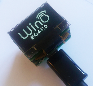
To use the Upgrade simply attach the Module on top of your WinoBOARD and connect it to a power supply (e.g. by using a Programming board or a USB-Upgrade)
Software / Library:
Please use the latest WinoBOARD integration from the Boardsmanager (at least 1.7.0). This library will include the libraries necessary to use the display.
Basic Examples:
The library is based on the Adafruit SSD1306 Library. To include the library please add this to your first lines of code:
#include "wino_oled.h"To initialize the display you can simply use:
display.start()For a complex example which shows the capability of the display please download this Arduino Sketch:
WinoBOARD OLED-Upgrade Example
Basic example to show the MCU temperature on your screen:
#include "wino_oled.h"

void setup(){

  display.start();  // Initialize the display
  display.invertDisplay(true); //inverts the colors of the display
  display.display(); // Show image buffer on the display hardware. The predefined buffer is the WinoBOARD logo.
  delay(10000); //wait for 10 seconds
  display.invertDisplay(false);
  display.clearDisplay();  // Clears the display buffer.
}

void loop(){
 display.clearDisplay(); //clears display
 display.setTextSize(1); //set to small text size for upper line
 display.setTextColor(WHITE);
 display.println(""); //write empty line
 display.setCursor(5,5);
 display.println("current temperature:"); //draws line
 display.setTextSize(3); //set to bigger text
 display.setCursor(5,28);
 float temperatur = float(getTemp())/10; //reads MCU temperature
 display.println(String(temperatur) + "C"); //write temperature in °C
 display.display(); //displays text
 delay(1000); // delay for next refresh
}
Show a custom picture on the screen:
There is an easy way to show custom pictures on the screen. You can use our Picture to Array converter to create a picture array and show it by using the writebuffer function:
#include "wino_oled.h"

uint8_t picture[64 * 128 / 8] = {
0xFF, 0xFF, 0xFF, 0xFF, 0xFF, 0xFF, 0xFF, 0xFF, 0xFF, 0xFF, 0xFF, 0xFF, 0xFF, 0xFF, 0xFF, 0xFF,
0xFF, 0xFF, 0xFF, 0xFF, 0xFF, 0xFF, 0xFF, 0xFF, 0xFF, 0xFF, 0xFF, 0xFF, 0xFF, 0xFF, 0xFF, 0xFF,
0xFF, 0xFF, 0xFF, 0xFF, 0xFF, 0xFF, 0xFF, 0xFF, 0xFF, 0xFF, 0xFF, 0xFF, 0xFF, 0xFF, 0xFF, 0xFF,
0xFF, 0xFF, 0xFF, 0xFF, 0xFF, 0xFF, 0xFF, 0xFF, 0xFF, 0xFF, 0xFF, 0xFF, 0xFF, 0xFF, 0xFF, 0xFF,
0xFF, 0xFF, 0xFF, 0xFF, 0xFF, 0xFF, 0xFF, 0xFF, 0x7F, 0x7F, 0x7F, 0x7F, 0x7F, 0x3F, 0x3F, 0x3F,
0x3F, 0x3F, 0x3F, 0x3F, 0x3F, 0x3F, 0x1F, 0x1F, 0x1F, 0x1F, 0x1F, 0x1F, 0x1F, 0x3F, 0x3F, 0x3F,
0x3F, 0x3F, 0x3F, 0x3F, 0x3F, 0x3F, 0x7F, 0x7F, 0x7F, 0x7F, 0x7F, 0xFF, 0xFF, 0xFF, 0xFF, 0xFF,
0xFF, 0xFF, 0xFF, 0xFF, 0xFF, 0xFF, 0xFF, 0xFF, 0xFF, 0xFF, 0xFF, 0xFF, 0xFF, 0xFF, 0xFF, 0xFF,
0xFD, 0xF1, 0xC1, 0x01, 0x01, 0x03, 0x0F, 0x3F, 0x7F, 0xFF, 0xF3, 0xC3, 0x07, 0x07, 0x07, 0x0F,
0x0F, 0x0F, 0x0F, 0x1F, 0x1F, 0x1F, 0x1F, 0x1F, 0x1F, 0x3F, 0x3F, 0x3F, 0x3F, 0x3F, 0x3F, 0x3F,
0x3F, 0x3F, 0x3F, 0x3F, 0x3F, 0x3F, 0x3F, 0x3F, 0x3F, 0x3F, 0x3F, 0x1F, 0x1F, 0x1F, 0x1F, 0x1F,
0x1F, 0x1F, 0x0F, 0x0F, 0x0F, 0x0F, 0x0F, 0x07, 0x07, 0x07, 0x07, 0x03, 0x03, 0x03, 0x03, 0x01,
0x01, 0x01, 0x01, 0x00, 0x00, 0x00, 0x00, 0x00, 0x00, 0x00, 0x00, 0x00, 0x00, 0x00, 0x00, 0x00,
0x00, 0x80, 0x80, 0x80, 0x80, 0x00, 0x00, 0x80, 0x80, 0xC0, 0x40, 0x40, 0x40, 0x40, 0x40, 0xC0,
0x80, 0x80, 0x00, 0x00, 0x80, 0x80, 0x80, 0x80, 0x80, 0x80, 0x80, 0x80, 0x00, 0x00, 0x00, 0x01,
0x01, 0x01, 0x03, 0x07, 0x1F, 0x7F, 0xFF, 0xFF, 0xFF, 0xFF, 0xFF, 0xFF, 0xFF, 0xFF, 0xFF, 0xFF,
0xFF, 0xFF, 0xFF, 0xFF, 0xFE, 0xF8, 0xE0, 0x80, 0x00, 0x01, 0x07, 0x1F, 0x7F, 0xFC, 0xF8, 0xE0,
0x80, 0x00, 0x00, 0x00, 0x00, 0x00, 0x00, 0x40, 0xC0, 0xC0, 0x40, 0x40, 0x40, 0x40, 0x40, 0x80,
0x80, 0x80, 0x00, 0x00, 0x00, 0x80, 0x80, 0x80, 0x00, 0x00, 0x00, 0x00, 0x00, 0x00, 0x00, 0xC0,
0xC0, 0x00, 0x00, 0x00, 0xC0, 0xC0, 0x60, 0x20, 0x20, 0x20, 0x20, 0x30, 0x70, 0x20, 0x00, 0x00,
0x30, 0xF8, 0xF8, 0x8C, 0x04, 0x04, 0x04, 0x04, 0x0C, 0x0C, 0xC0, 0xC0, 0xC3, 0x0F, 0x3F, 0xF9,
0xE9, 0x49, 0x48, 0x44, 0x44, 0x64, 0x20, 0x21, 0x03, 0x13, 0x12, 0x32, 0x22, 0x22, 0x22, 0x22,
0x22, 0x14, 0x1C, 0x1C, 0x18, 0x03, 0x03, 0x12, 0x14, 0x24, 0x24, 0x24, 0x25, 0x21, 0x0B, 0x4A,
0x70, 0x70, 0x60, 0x00, 0x00, 0x00, 0x01, 0x07, 0x0F, 0x3F, 0xFF, 0xFF, 0xFF, 0xFF, 0xFF, 0xFF,
0xFF, 0xFF, 0xFF, 0xFF, 0xFF, 0xFF, 0xFF, 0xFF, 0xFE, 0xFC, 0xF0, 0xC0, 0x00, 0x00, 0x03, 0x0F,
0x3F, 0xFE, 0xF8, 0xF0, 0xC0, 0x00, 0x00, 0x00, 0x00, 0x05, 0x0D, 0x0A, 0x12, 0x12, 0x12, 0x12,
0x04, 0x25, 0x25, 0x3C, 0x38, 0x10, 0x03, 0x0F, 0x1E, 0x3C, 0x30, 0x20, 0x20, 0x20, 0x20, 0x21,
0x27, 0x3F, 0x3C, 0x18, 0x01, 0x07, 0x0F, 0x0C, 0x18, 0x10, 0x18, 0x08, 0x08, 0x08, 0x0E, 0x06,
0x06, 0x00, 0x01, 0x03, 0x03, 0x02, 0x02, 0x02, 0x01, 0x01, 0x01, 0x01, 0x00, 0x00, 0x00, 0x00,
0x00, 0x00, 0x00, 0x00, 0x00, 0x00, 0x00, 0x00, 0x80, 0x80, 0x80, 0x80, 0x80, 0x80, 0xC0, 0xC0,
0xC0, 0xC0, 0xC0, 0xC0, 0xC0, 0xC0, 0xC0, 0xC0, 0xC0, 0xC0, 0xC0, 0xC0, 0xC0, 0xC0, 0xC0, 0xC0,
0x80, 0x80, 0x80, 0x80, 0x80, 0x80, 0x00, 0x00, 0x00, 0x00, 0x00, 0x03, 0x0F, 0x1F, 0x7F, 0xFF,
0xFF, 0xFF, 0xFF, 0xFF, 0xFF, 0xFF, 0xFF, 0xFF, 0xFF, 0xFF, 0xFF, 0xFF, 0xFF, 0xFC, 0xF0, 0xE0,
0x80, 0x00, 0x01, 0x07, 0x1F, 0x7F, 0xFC, 0xF8, 0xF8, 0xF8, 0xF8, 0xF0, 0xF0, 0xF0, 0xE0, 0xE0,
0xE0, 0xE0, 0xE0, 0xC0, 0xC0, 0xC0, 0xC0, 0xC0, 0xC0, 0xC0, 0xC0, 0xC0, 0x80, 0x80, 0x80, 0x80,
0x80, 0x80, 0x80, 0x80, 0xC0, 0xC0, 0xC0, 0xC0, 0xC0, 0xC0, 0xC0, 0xC0, 0xE0, 0xE0, 0xE0, 0xE0,
0xE0, 0xE0, 0xF0, 0xF0, 0xF0, 0xF0, 0xF8, 0xF8, 0xF8, 0xF8, 0xFC, 0xFC, 0xFC, 0xFC, 0xFC, 0xFE,
0xFE, 0xFE, 0xFE, 0xFF, 0xFF, 0xFF, 0xFF, 0xFF, 0xFF, 0xFF, 0xFF, 0xFF, 0xFF, 0xFF, 0xFF, 0xFF,
0xFF, 0xFF, 0xFF, 0xFF, 0xFF, 0xFF, 0xFF, 0xFF, 0xFF, 0xFF, 0xFF, 0xFF, 0xFF, 0xFF, 0xFF, 0xFF,
0xFF, 0xFF, 0xFF, 0xFF, 0xFF, 0xFF, 0xFF, 0xFF, 0xFF, 0xFF, 0xFE, 0xFE, 0xFE, 0xFE, 0xFC, 0xFD,
0xFF, 0xFF, 0xFF, 0xFF, 0xFF, 0xFF, 0xFF, 0xFF, 0xFF, 0xFF, 0xFF, 0xFF, 0xFF, 0xFF, 0xFF, 0xFF,
0xFF, 0xFE, 0xF8, 0xE0, 0xC0, 0x00, 0x01, 0x03, 0x0F, 0x3F, 0xFF, 0xFF, 0xFF, 0xFF, 0xFF, 0xFF,
0xFF, 0xFF, 0xFF, 0xFF, 0xFF, 0xFF, 0xFF, 0xFF, 0xFF, 0xFF, 0xFF, 0xFF, 0xFF, 0xFF, 0xFF, 0xFF,
0xFF, 0xFF, 0xFF, 0xFF, 0xFF, 0xFF, 0xFF, 0xFF, 0xFF, 0xFF, 0xFF, 0xFF, 0xFF, 0xFF, 0xFF, 0xFF,
0xFF, 0xFF, 0xFF, 0xFF, 0xFF, 0xFF, 0xFF, 0xFF, 0xFF, 0xFF, 0xFF, 0xFF, 0xFF, 0xFF, 0xFF, 0xFF,
0xFF, 0xFF, 0xFF, 0xFF, 0xFF, 0xFF, 0xFF, 0xFF, 0xFF, 0xFF, 0xFF, 0xFF, 0xFF, 0xFF, 0xFF, 0xFF,
0xFF, 0xFF, 0xFF, 0xFF, 0xFF, 0xFF, 0xFF, 0xFF, 0xFF, 0xFF, 0xFF, 0xFF, 0xFF, 0xFF, 0xFF, 0xFF,
0xFF, 0xFF, 0xFF, 0xFF, 0xFF, 0xFF, 0xFF, 0xFF, 0xFF, 0xFF, 0xFF, 0xFF, 0xFF, 0xFF, 0xFF, 0xFF,
0xFF, 0xFF, 0xFF, 0xFF, 0xFF, 0xFF, 0xFF, 0xFF, 0xFF, 0xFF, 0xFF, 0xFF, 0xFF, 0xFF, 0xFF, 0xFF,
0xFF, 0xFF, 0xFF, 0xFF, 0xFF, 0xFF, 0xFC, 0xF0, 0xC0, 0x80, 0x00, 0x03, 0x0F, 0x1F, 0x7F, 0xFF,
0xFF, 0xFF, 0xFF, 0xFF, 0xFF, 0xFF, 0xFF, 0xFF, 0xFF, 0xFF, 0xFF, 0xFF, 0xFF, 0xFF, 0xFF, 0xFF,
0xFF, 0xFF, 0xFF, 0xFF, 0xFF, 0xFF, 0xFF, 0xFF, 0xFF, 0xFF, 0xFF, 0xFF, 0xFF, 0xFF, 0xFF, 0xFF,
0xFF, 0xFF, 0xFF, 0xFF, 0xFF, 0xFF, 0xFF, 0xFF, 0xFF, 0xFF, 0xFF, 0xFF, 0xFF, 0xFF, 0xFF, 0xFF,
0xFF, 0xFF, 0xFF, 0xFF, 0xFF, 0xFF, 0xFF, 0xFF, 0xFF, 0xFF, 0xFF, 0xFF, 0xFF, 0xFF, 0xFF, 0xFF,
0xFF, 0xFF, 0xFF, 0xFF, 0xFF, 0xFF, 0xFF, 0xFF, 0xFF, 0xFF, 0xFF, 0xFF, 0xFF, 0xFF, 0xFF, 0xFF,
0xFF, 0xFF, 0xFF, 0xFF, 0xFF, 0xFF, 0xFF, 0xFF, 0xFF, 0xFF, 0xFF, 0xFF, 0xFF, 0xFF, 0xFF, 0xFF,
0xFF, 0xFF, 0xFF, 0xFF, 0xFF, 0xFF, 0xFF, 0xFF, 0xFF, 0xFF, 0xFF, 0xFF, 0xFF, 0xFF, 0xFF, 0xFF,
0xFF, 0xFF, 0xFF, 0xFF, 0xFF, 0xFF, 0xFF, 0xFF, 0xFF, 0xFF, 0xFE, 0xF8, 0xF8, 0xF8, 0xF8, 0xF9,
0xFF, 0xFF, 0xFF, 0xFF, 0xFF, 0xFF, 0xFF, 0xFF, 0xFF, 0xFF, 0xFF, 0xFF, 0xFF, 0xFF, 0xFF, 0xFF,
0xFF, 0xFF, 0xFF, 0xFF, 0xFF, 0xFF, 0xFF, 0xFF, 0xFF, 0xFF, 0xFF, 0xFF, 0xFF, 0xFF, 0xFF, 0xFF,
0xFF, 0xFF, 0xFF, 0xFF, 0xFF, 0xFF, 0xFF, 0xFF, 0xFF, 0xFF, 0xFF, 0xFF, 0xFF, 0xFF, 0xFF, 0xFF,
0xFF, 0xFF, 0xFF, 0xFF, 0xFF, 0xFF, 0xFF, 0xFF, 0xFF, 0xFF, 0xFF, 0xFF, 0xFF, 0xFF, 0xFF, 0xFF,
0xFF, 0xFF, 0xFF, 0xFF, 0xFF, 0xFF, 0xFF, 0xFF, 0xFF, 0xFF, 0xFF, 0xFF, 0xFF, 0xFF, 0xFF, 0xFF,
0xFF, 0xFF, 0xFF, 0xFF, 0xFF, 0xFF, 0xFF, 0xFF, 0xFF, 0xFF, 0xFF, 0xFF, 0xFF, 0xFF, 0xFF, 0xFF};

void setup(){
  display.start();  // Initialize the display
  display.writebuffer(picture);
  display.display(); // Show image buffer on the display hardware. The predefined buffer is the WinoBOARD logo.
}

void loop(){
}
For further information please also have a look at the Adafruit website:
Adafruit OLED library and examples
4. Widgets - the easy way to control your WinoBOARD.
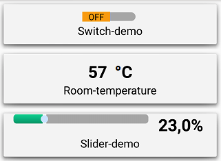
Introduction:
Widgets are controls to communicate to one ore more devices. There are currently three types of Widgets:
Status: The Status widget is a read-only display of a specific value like a Temperature display.
Slider: The slider is used to set a value in a specific range like setting a Voltage output.
Switch: This switch can be used for a simple on/off or other 2-state controls e.g. switching a Light on/off.
WinoBOARD code Example:
(please make sure your WinoBOARD is connected to WIFI to use this example)
#include "widgets.h"
#include "wino.h"

void setup() {
wifi.on(115200);
wifi.wait(20000);

SerialUSB.println("Connected to IP:" + wifi.getip());

widget.start();
widget.addStatus(0, "Temperature", "C");
widget.addSlider(1, "LED-Brightness", "%", 0, 100);
widget.addSwitch(2, "LED", "on", "off");
}

void loop() {
widget.write(0, float(getTemp())/10); //reads MCU temperature
analogWrite(2, widget.read(1)/100*127*widget.read(2)); //this controls the voltage of the LED on Pin 2
widget.refresh();
}
4.1. Widgets Library
widget.start()
Opens TCP-Server and prepares Module for Widgets communication
widget.addStatus(ID,Description,Unit)
Adds a Status-Widget
ID = ID as Integer -> ID´s have to be continious and starting with 0 like 0,1,2,3,...
Description = Name of the Widget as String
Unit = Name of unit of the displayed value (e.g "°C")
Example:
widget.addStatus(0, "Temperature", "C"); /*please check ID*/
widget.addSlider(ID,Description,Unit,Min.Value,Max.Value)
Adds a Slider-Widget
ID = ID as Integer -> ID´s have to be continious and starting with 0 like 0,1,2,3,...
Description = Name of the Widget as String
Unit = Name of unit of the displayed value (e.g "°C")
Min.Value = The minimum value of the slider
Max.Value = The maximum value of the slider
Example:
widget.addSlider(0, "Voltage", "V", 0, 3.3); /*please check ID*/
widget.addSwitch(ID,Description,On-Description,Off-Description )
Adds a Switch-Widget
ID = ID as Integer -> ID´s have to be continious and starting with 0 like 0,1,2,3,...
Description = Name of the Widget as String
On-Description = This describes the state of the switch if the switch is "ON"
Off-Description = This describes the state of the switch if the switch is "Off"
Example:
widget.addSwitch(0, "Light", "on", "off"); /*please check ID*/
4.2. Control you WinoBOARD using your Smartphone or Tablet.
1. Home tab
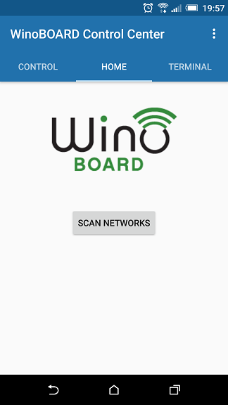
To scan for available devices hit the "scan networks" button
(Please not the the IP-Scan range is set in the Settings menu)
2. Control tab
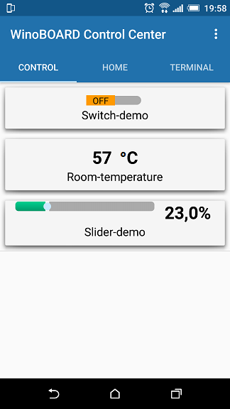
This tab should show any available Widgets of all connected devices.
(The refresh time can be adjusted in the Settings menu)
3. Terminal tab
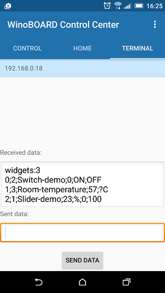
The Terminal can be used to communicate to your device by TCP-IP. Any response from the module will be shown in the "Received data" window.
5. Examples
5.1. Sleep mode and power saving functions
MCU Sleep Function:
sleep(mode)
mode:
Set the sleep mode. There are following sleep modes available:
- 0: IDLE0 (CPU clock off)
- 1: IDLE1 (CPU clock, AHB clock off)
- 2: IDLE2 (CPU clock, AHB clock, APB clock off)
- 3: STANDBY (MCU is off and waiting for Interrupt)
NOTE: To wakeup the device from STANDBY use only LOW or HIGH interrupt events (RISING, FALLING and CHANGE won´t work in this case)
Example:
#include "wino.h"
bool wake = true;

void setup() {
  // put your setup code here, to run once:
  wifi.off(); //Turn off WIFI to save power
  pinMode(8, INPUT); //Pin 4 will be the wakeup pin
  pinMode(2, OUTPUT); //LED is set to output to show if device is sleeping (LED=off)
  attachInterrupt(8, wakeup, HIGH); //Set interrupt to wakup device from sleep
}

void loop() {
  // put your main code here, to run repeatedly:
  if (wake == false){
    digitalWrite(2, LOW);
    sleep(3); //send MCU into deep sleep
  } else
    {
      digitalWrite(2, HIGH); //Turn on LED to show that device is alive
      wake = false;
      delay(5000); //after 5 seconds the device will go into sleep mode again
  }
}

void wakeup() {          //this function is called when the intterupt is changing state
  wake = true;
}
5.2. How to use Interrupts on the WinoBOARD
Function:
attachInterrupt( Pin, Function, Event )
Pin:
The pin attached as interrupt. Available Pins are:
Digital Pins: 0, 1, 2, 3, 4, 5, 8, 9, 10, 11, 12, 13
Analog Pins: A0, A1, A2, A3, A4, A5, A7, A8
Function:
The function to call if event was triggered
Event:
- LOW: to trigger the interrupt whenever the pin is low,
- CHANGE: to trigger the interrupt whenever the pin changes value
- RISING: to trigger when the pin goes from low to high,
- FALLING: for when the pin goes from high to low.
- HIGH: to trigger the interrupt whenever the pin is high
NOTE: Only one event per pin can be triggered
Example:
bool state = LOW;   //just a variable to store the LED state
int ledPin = 2;     //PIN 2 is connected to the green onboard LED
int interruptPin = A3;  //this pin is the pin which triggers the interrupt event

void setup() {
pinMode(ledPin, OUTPUT);    //turn the LED-pin to an output pin
pinMode(interruptPin, INPUT_PULLUP);        //the normal state (unconnected) of input pin should be HIGH
attachInterrupt(interruptPin, blink, CHANGE);   //This function defines the Interrupt pin and the event
}

void loop() {
digitalWrite(ledPin, state);
}

void blink() {          //this function is called when the intterupt is changing state
  state = !state;       //change the actual state
}
5.3. Power on WIFI
This example shows how to switch the WIFI module on/off and set the bootmode of the module
The WIFI_EN_PIN is switching the module on/off (high=on, low=off)
Pin 13 is setting the bootmode of the module (high=normal mode, low=flashing mode). This pin is pulled high so it´s usually not necessary to include this pin in your code.
void setup() {

  pinMode(2, OUTPUT); //LED is connected to Pin2
  pinMode(WIFI_EN_PIN, OUTPUT); //This pin controls the power of the WIFI module (HIGH = ON)
  pinMode(13, OUTPUT); //This pin sets the WIFI mode, 0 = flashmode, 1 = normal mode

 //Preparing Wifi-module
 digitalWrite(WIFI_EN_PIN, LOW); //turns WIFI module off
 pinMode(13, OUTPUT); //set module to normal mode
 delay(100);              // wait a short time
 digitalWrite(WIFI_EN_PIN, HIGH); //turns WIFI module on
}

void loop() {

}
5.4. Print IP
Description:
This example is waiting for the module to connect and print the received IP-Address in the USB-Terminal.
Command:
String answer;
String ip = "";
void setup() {
  // put your setup code here, to run once:
  pinMode(2, OUTPUT);
  pinMode(13, OUTPUT);
  pinMode(WIFI_EN_PIN, OUTPUT);

  Serial.begin(115200); //Opens serial connection to WIFI module
  SerialUSB.begin(115200); //Opens USB-Serial connection for terminal

 //Preparing Wifi-module
 digitalWrite(WIFI_EN_PIN, LOW); //turns WIFI module off
 digitalWrite(13, HIGH); //set module to normal mode
 delay(100);              // wait a short time
 digitalWrite(WIFI_EN_PIN, HIGH); //turns WIFI module on

    //wait until the module is ready
    while (!Serial.find("ready\r\n")) {}
    SerialUSB.write("Module is ready\r\n");

    //Set module to Station mode and wait for reply
    Serial.println("AT+CWMODE=1");
    while (!Serial.find("OK\r\n")) {}
    SerialUSB.println("Module changing to Station mode");
    //delay(100);

    //Waiting for IP-Address
    while (!Serial.find("WIFI GOT IP")) {SerialUSB.println("Waiting for IP-Address"); delay(200);}
    SerialUSB.println("got IP-Address");

    //Reading IP-Address
    Serial.println("AT+CIFSR");
}

void loop() {

while (Serial.available() > 0)
    {
        char received = Serial.read();
        answer.concat(received);
        if (answer.indexOf("\r\n") > -1 ){

          if (answer.indexOf("STAIP") > -1) {
            int starti = answer.indexOf('IP,"') + 1;
            ip = answer.substring(starti,answer.length() - 3);
          }
         answer="";
        }
        // Process message when new line character is recieved
    }

if (ip != "") {SerialUSB.println(ip); delay(1000);}

}
5.5. Show WIFI-Setup (enable AP-Mode)
Description:
This example shows how to set up the mode of the WIFI module by the CWMODE command. This example sets the module to CWMODE=3 which enables station and accesspoint mode.
Command:
void setup() {
  // put your setup code here, to run once:
  pinMode(2, OUTPUT);
  pinMode(13, OUTPUT);
  pinMode(WIFI_EN_PIN, OUTPUT);

  Serial.begin(115200); //Opens serial connection to WIFI module
  SerialUSB.begin(115200); //Opens USB-Serial connection for terminal

 //Preparing Wifi-module
 digitalWrite(WIFI_EN_PIN, LOW); //turns WIFI module off
 digitalWrite(13, HIGH); //set module to normal mode
 delay(100);              // wait a short time
 digitalWrite(WIFI_EN_PIN, HIGH); //turns WIFI module on

    //wait until the module is ready
    while (!Serial.find("ready\r\n")) {}
    SerialUSB.write("Module is ready\r\n");

    //Set module to Station&AP mode to enable WIFI Setup
    Serial.println("AT+CWMODE=3");
    while (!Serial.find("OK\r\n")) {}
    SerialUSB.println("Module changing to AP&Station mode");

}

void loop() {

}
5.6. Communication with WIFI-module by USB-Terminal
Description:
This example shows how to communicate directly to the WIFI module by using the Serial Monitor.
Command:
byte byte1Read;
byte byte2Read;

void setup() {
SerialUSB.begin(115200);  //Serial connection to Serial Monitor
Serial.begin(115200);  //Serial connection to WIFI module
delay(5000);  //This delays the start of the module so all information can be captured in the Serial monitor
pinMode(WIFI_EN_PIN, OUTPUT);
digitalWrite(WIFI_EN_PIN, HIGH); // Turns WIFI module on

void loop() {

    if (SerialUSB.available()) {
        Serial.write(SerialUSB.read()); //Reads data from Serialmonitor and sends it to WIFI module
    }
    if (Serial.available()) {
        SerialUSB.write(Serial.read());   //Reads WIFI module data from  and sends it to Serialmonitor
    }
}
5.7. TCP-Server
Description:
PLEASE ONLY USE THIS CODE IF YOU HAVE THE MODULE CONNECTED TO YOUR NETWORK.
This example shows how to communicate by a TCP-Server socket (module on server side).
To connect to the Server please use a TCP Client (like Putty) and connect to IP: 192.168.0.99 PORT:7777
You are now able to control the LED on the Wino board by the commands "led on" or "led off"
Command:
int LED_PIN = 2;

//TCP Server configuration
String port = "7777";
String clientIp = "192.168.0.99"; //This uses static IP

int listening = 0;
String answer = "";
bool wifi = false;

void setupWifi(void)
{
  //test if the module is ready
  while (!Serial.find("ready\r\n")) {}

  Serial.println("AT+CWMODE=3");
  while (!Serial.find("OK\r\n")) {}
  delay(100);

  Serial.println("AT+CWDHCP=1,1");
  while (!Serial.find("OK\r\n")) {}

  //set AP IP-adress
  Serial.println("AT+CIPAP=\"192.168.4.1\"");
  while (!Serial.find("OK\r\n")) {}

  //check for ip address
  while (!Serial.find("WIFI GOT IP")) {
  };

  //set static IP-address
  Serial.println("AT+CIPSTA=\""+ clientIp +"\"");
  delay(100);
  while (!Serial.find("OK\r\n")) {}

  //change to stationary mode and close AP
  Serial.println("AT+CWMODE=1");
  while (!Serial.find("OK\r\n")) {}

 digitalWrite(LED_PIN, HIGH);
 wifi = true;

}

void listenTCP() {

 if (listening == 0) {
  Serial.println("AT+CIPMUX=1");
  while (!Serial.find("OK\r\n")) {}
  delay(100);

  String connecttcp = "AT+CIPSERVER=1," + port;
  Serial.println(connecttcp);

  while (!Serial.find("OK\r\n")) {}

  listening = 1;
  }

      while (Serial.available() > 0) {
      char character = Serial.read();
      answer.concat(character);
      if (answer.indexOf("CLOSED\r\n") > -1) {listening = 0;}
      if (answer.indexOf("+IPD") > -1 and answer.indexOf("\r\n") > -1) {
          int starti = answer.indexOf(":") + 1;
          int endi = answer.indexOf("\r");
          answer = answer.substring(starti,endi);
      }
      if (answer.indexOf("\r\n") > -1) {answer ="";}
      }

}

void setup() {

  pinMode(LED_PIN, OUTPUT);
  pinMode(WIFI_EN_PIN, OUTPUT);

  pinMode(12, OUTPUT);
  digitalWrite(12, HIGH);

  digitalWrite(WIFI_EN_PIN, LOW);
  delay(100);
  digitalWrite(WIFI_EN_PIN, HIGH);

  Serial.begin(115200);

  setupWifi();

}

String runcommand(String command) {

  String cmd = command.substring(0, command.indexOf(" "));
  String stringvalue = command.substring(command.indexOf(" ") + 1, command.length());
  float value = stringvalue.toFloat();
  if (stringvalue == "on") {value = 1;}
  if (stringvalue == "off") {value = 0;}
  Serial.println(value);
 //parses incoming TCP-data

  //WRITE DIGITAL PINS
  if (stringvalue == "on" or stringvalue == "off") {
    if (cmd == "led") {pinMode(LED_PIN, OUTPUT); digitalWrite(LED_PIN, value); return "OK\r\n";}
  }
}

void loop()
{

  if (wifi == 1) {
   listenTCP();
  }

  delay(10);
}
6. Hardware guide
This section provide you Harware related data to the WinoBOARD
6.1. Layout
Pin layout
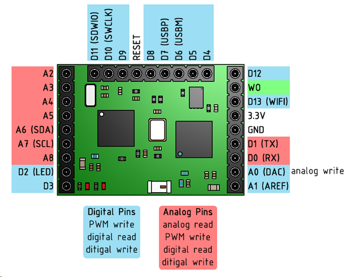
default SPI Pins
MISO----->A5
MOSI----->A2
SCK------->A3
SS -------->A4
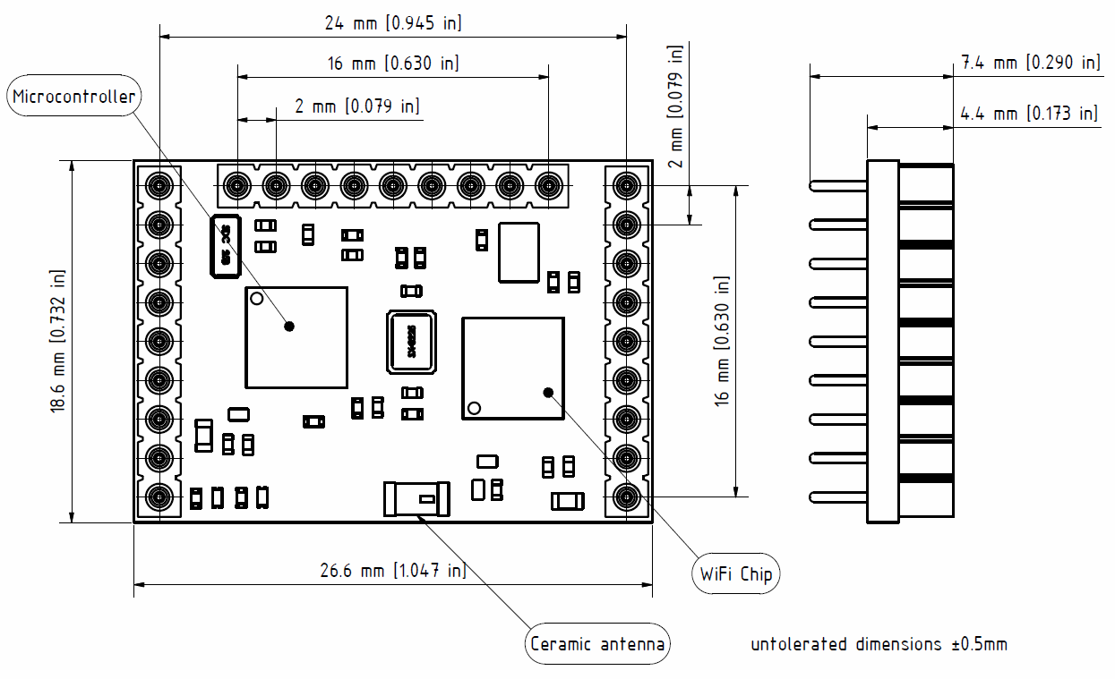
Dimension sheet
6.2. Specification
| Description | Value |
|---|---|
| Microcontroller | Atmel ATSAMD21 |
| Supply Voltage | 3.3V |
| Digital I/O Pins | 15 |
| Analog I/O Pins | 6 x 12 Bit ADC, 1 x 10 Bit DAC |
| max. DC Current per I/O pins | 7mA |
| Flash Memory | 128 kB |
| SRAM | 16 kB |
| Microcontroller clock speed | 48 MHz |
| WIFI-Module | ESP8266EX |
| Wireless standard | 802.11 b/g/n |
| Modes | P2P, soft-AP |
| Network features | TCP-IP / UDP communication, Static IP, DHCP |
| Interface | 27 I/O Pin stackable header |
| Dimensions | 18,6 x 26,6 mm |
Power consumption
| Part | Mode | Power consumption |
|---|---|---|
| Microcontroller (SAMD21) | on | 1 - 5 mA |
| Microcontroller (SAMD21) | standby | 3 mA |
| WIFI-Chip (ESP8266) | send | 150 mA |
| WIFI-Chip (ESP8266) | receive | 50 mA |
| WIFI-Chip (ESP8266) | sleep | 1 - 15 mA |
| WIFI-Chip (ESP8266) | deep sleep | 0.01 mA |
| WIFI-Chip (ESP8266) | off | 0.0005 mA |
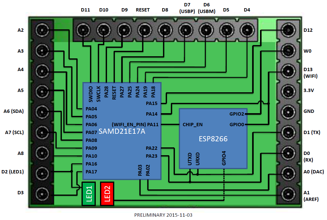
Shematic (simplified)
7. FAQ
8. Troubleshooting
8.1. Uploading code is very slow
In most cases this is a USB-connection issue.
- Please connect the Board directly to the PC (without using an USB-Hub)
- Check if the USB-port is set to 115200 bauds (like in the device manager)